 Henry Ho
Holographic Display : Part 2
This was based on research by USC’s Institute of Creative Technologies. Their published research papers are here.
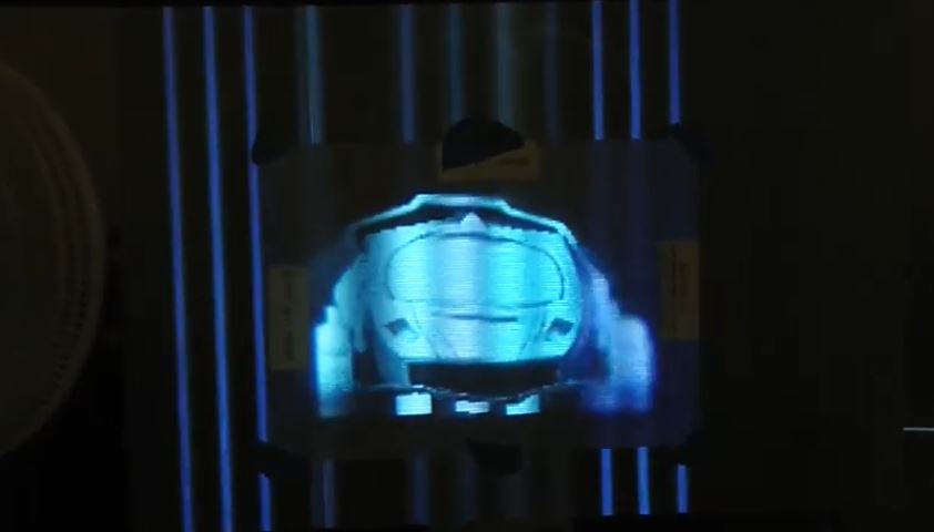
This time around, I was able to create a functional prototype using an array of cheap projectors (prices ranging from $30 to $80 on Amazon). There were no dangerous moving parts, and better still, I replaced the aluminum sheet with an anisotropic light diffuser sheet on top of a lenticular sheet. This was the main viewing screen.
The lenticular sheet slices up the image projected from each of the projectors by diffracting their rays into different directions so otherwise overlapping rays from multiple projectors don’t diffuse in the same direction. This creates a vertically sliced up image for the end user with each stripe delivered from different projectors. Notice in the image above how the areas without the anisotropic light diffuser sheet are stripes of light with bigger stripes of darkness in between. Those dark stripes are from the rays being diffracted into a different direction by the lenticular sheet. The diffuser sheet blends neighboring rays traveling in slightly different directions to fill in the gaps in between to fill in the image.
Here is the mishmash of cheap projectors I used.
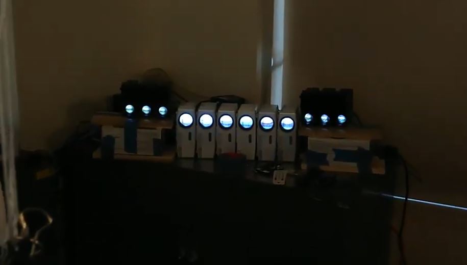
They are all pointed dead center at the main viewing screen, with each cheap projector driven by an even cheaper Android TV box running a Unity 3D application. The Android TV boxes are all networked together via Ethernet and a big ol’ Cisco switch that I got on eBay for around $70. A separate Unity app running on my computer hosts a multiplayer gaming session to which all the Android TV boxes connect. This is how the 3D model’s animations are synchronized across all the projectors.
Then there’s the complicated matter of calibration. I can’t physically align all the projectors to point directly at the center of the main viewing screen perfectly, and even then, each projector is shooting from a different angle, creating a distorted image onto the main viewing screen. So in order for their images to all overlay on top of each other perfectly, I have to perform a homography matrix calibration. I had no idea what homography was prior to this, and apparently neither does spell-check.

This is done by having each projector take turns displaying a square box on the main viewing screen. A webcam pointed directly at the main viewing screen records the corner positions of each of the square boxes from each projector, chooses the most un-distorted square box and computes the homography matrices for each of the other projectors to line up their corners with the most un-distorted box.
Once all that was done, I had to create a vertex shader that distorts the geometry of the 3D model to match the trajectory of light from each point of the projector through the main viewing screen. This is better visualized by one of the diagrams in USC’s research paper:
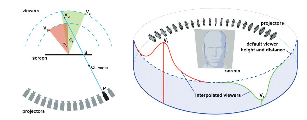
Fortunately, the good guys and gals at USC had gone over this shader in detail in their previous research paper regarding the spinning volumentric display. In it was very useful psuedo-code that I used to implement my own Unity 3D shader.
Here’s the result:
There’s a loss of resolution and brightness at the outer edges of the viewing angles because the cheapest projectors were used for those outer edges.
You can see that more clearly here in this video:
And here USC’s original demo that they published. It is of much higher quality as their projectors are much smaller in size, and as a result can be more densely packed at closer distances to the main viewing screen. This means that they can pack way more stripes together, creating a more seamless image.